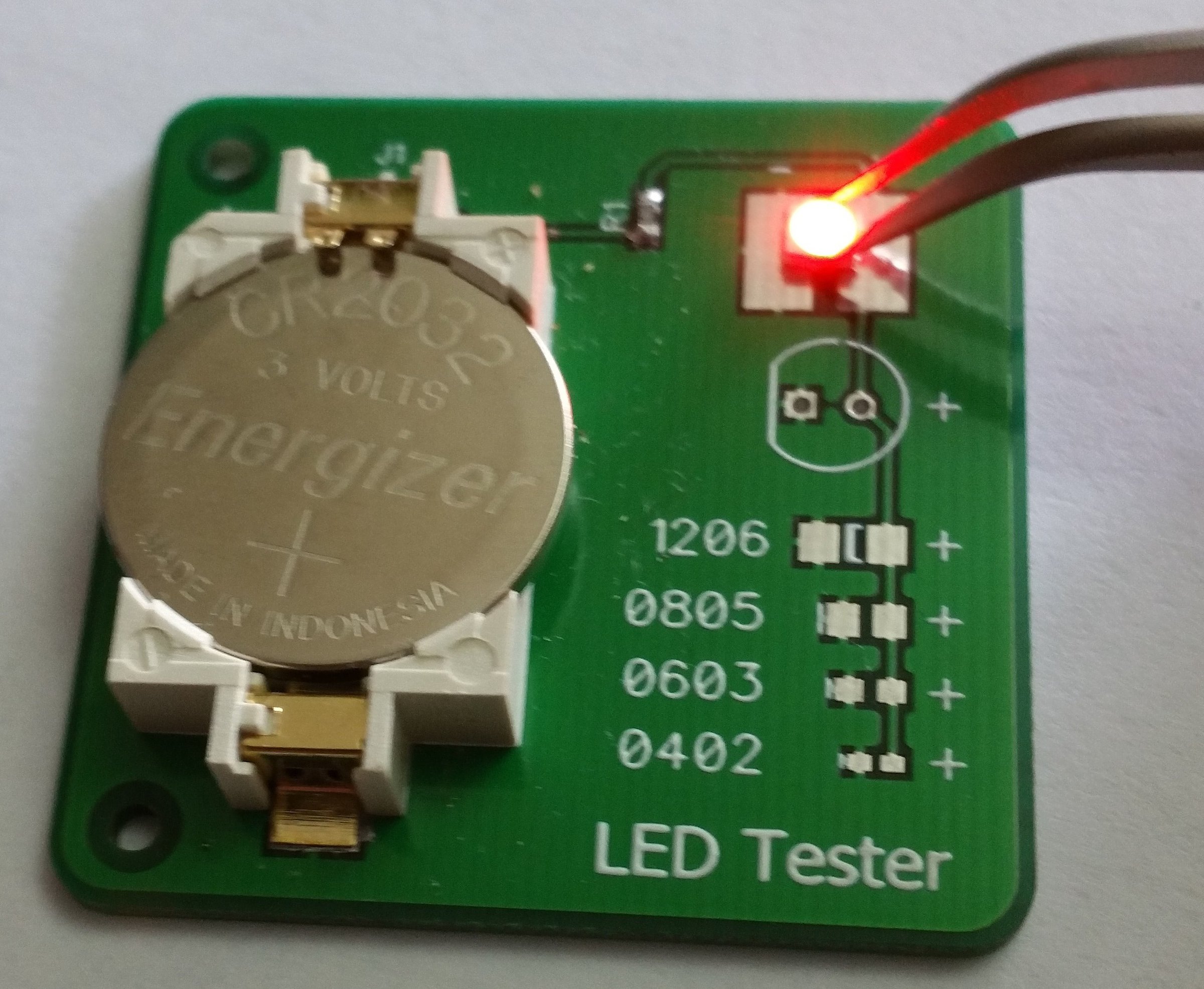
Led Tester Diy Use. The continuity tester we will build that lights up an led when there is continuity is shown below. The device is actually a simple led and a cell circuit, where the led is made to switch by passing the cell voltage to.

The voltmeter is based on single icl7107 chip and may be fitted on a small 3cm x 7cm printed circuit board. It is very dangerous to use 230v ac supply on breadboard. Be sure that the two probes do not touch each other during this test, and that the cathode and anode do not touch each other.
U1’S Output Directly Drives A Power Mosfet (Q1) That Switches The Current Through Power Inductor (L1).
For testing the transistor, its terminals should be connected exactly as give in the table,. These cover all of the major required electrical testing functions for diy household or professional electrical measurement situations, with each element offering valuable features for testing. Simple transistor tester (contains both circuit diagram and pcb lay out) 3.
Complete Code And Demonstration Video Are Given Below.
Most system can be calibrated and shipped within 1 week after. The 555 ic (u1) is wired as an astable oscillator at a frequency (around 68khz) determined by rc components (r1, r2 and c1). Which can measure the voltage at the third range are:
The Small Size Of The Pcb (75Mm X 19Mm) Makes It Ideal For Handheld.
Rf safe's diy circuit is the simplest detector for microwave radiation. 24v to 220v 1000w dc ac sine wave inverter for photovoltaic solar system. But if you probe a computerized circuit with your old incandescent test light, you can fry some sensitive and expensive electronics.
0.005 Is The Current In Amps.
5v to 8v dc converter power supply circuit diagram. (make sure to hook the red wire and black wires to the battery positive. It is very helpful when doing any kind of diy electrical work, such as wiring or installing light fixtures, or troubleshooting household devices, as it can warn you about an unsafe situation by detecting if electricity is still flowing before you find out the hard way.
I Soldered Extra Wires And Added The Alligator Clips.
The test is very simple, just put 9 volts battery for use as a reference voltage and a small size battery 1.5v aa to put in place a fully tested. Test equipment circuit diagrams and electronic projects note that all these links are external and we cannot provide support on the circuits or offer any guarantees to their accuracy. To test your led, touch the tip of the black probe to the cathode, or shorter end of the led.
0 Comments